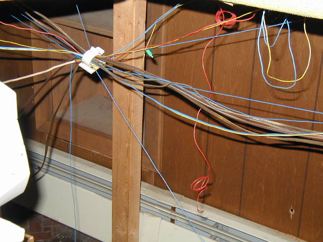
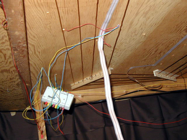
My original wiring was not very neat. As I added switches or track sections I just added the wires always promising myself I would go back and rewire everything.
Click on picture to return to description.
Not the way to wire a layout.
Click on picture to return to description.
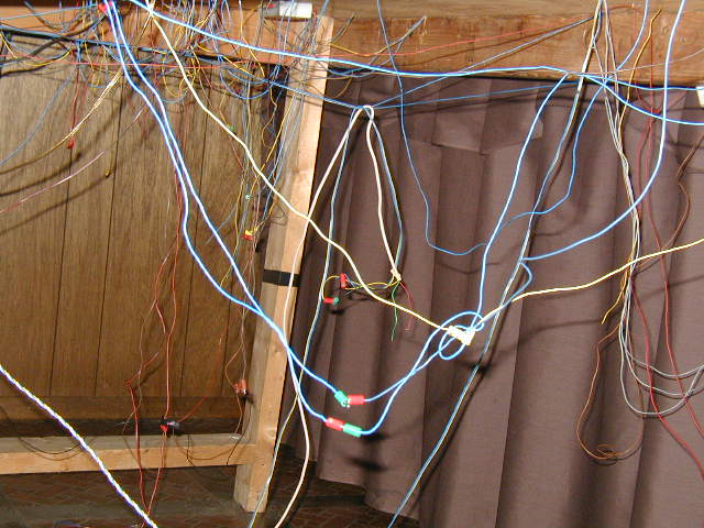
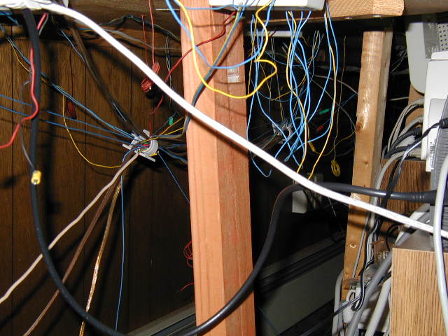
More of the original wiring.
Click on picture to return to description.
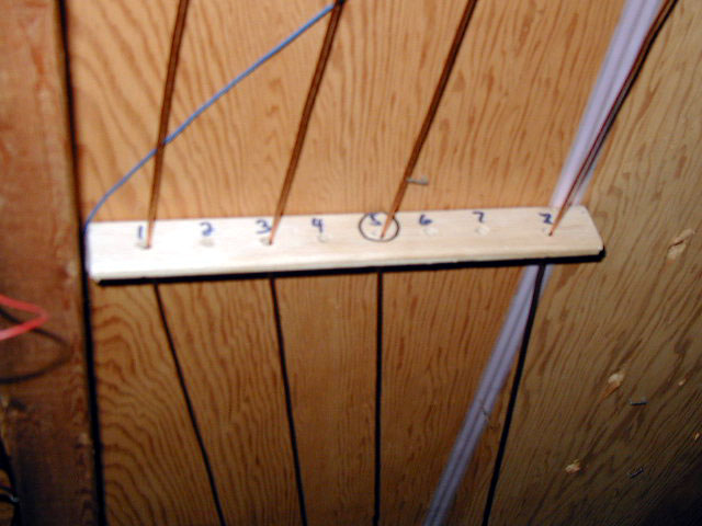
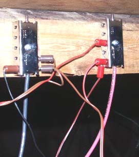
The new wiring. Note the neat arrangement of the power feeder wires (1,3 & 8) and the common ground (5).
Click on picture to return to description.
This red and brown feeds for this K83 will be soldered to the feeder and common ground wires and it will be remounted. The gray wire strip will be removed. It had been used to light the houses on the layout.
Click on picture to return to description.
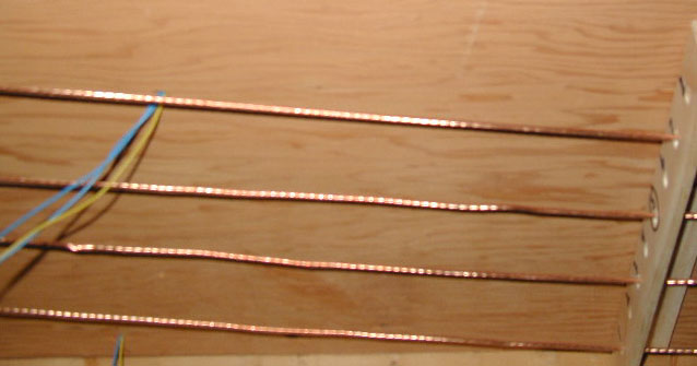
This is the proper way to wire a layout.
Click on picture to return to description.
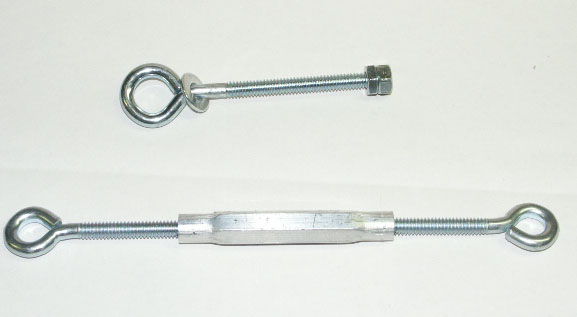
These are the eyelets and turnbuckles that were used to string the stranded-wire. See pictures below.
Click on picture to return to description.
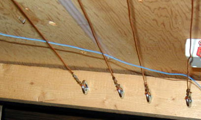
Each layout section was individually wired. First the wires were connected to eyelets.
Click on picture to return to description.
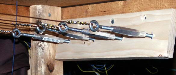
After being pulled through the looms the end of each wire was attached to a turnbuckle which keep the wires taunt.
Click on picture to return to description.

Using looms (made from corner molding) keeps the wires neat and properly separated. The extra wholes can be used for future power feeds if needed.
Click on picture to return to description.
I soldered an insulated wire to the Marklin distribution units. I then soldered these to a bare stranded-wire.
Click on picture to return to description.
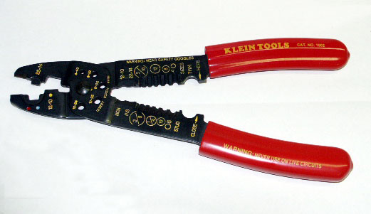
The stripping tool that I used to strip the insulation from the middle of the wire below.
Click on picture to return to description.
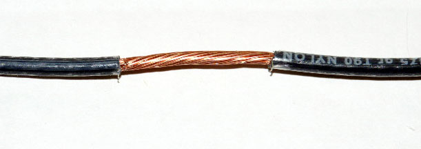
A sample of a stripped portion of the insulated wires I used for the industrial section only.
Click on picture to return to description.
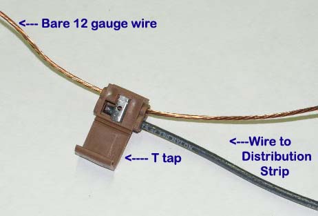
A T tap used to connect a distribution strip to the bare 12 gauge wires.
Click on picture to return to description.
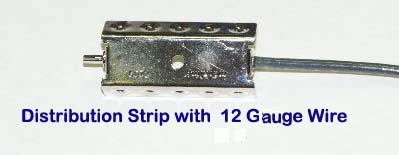
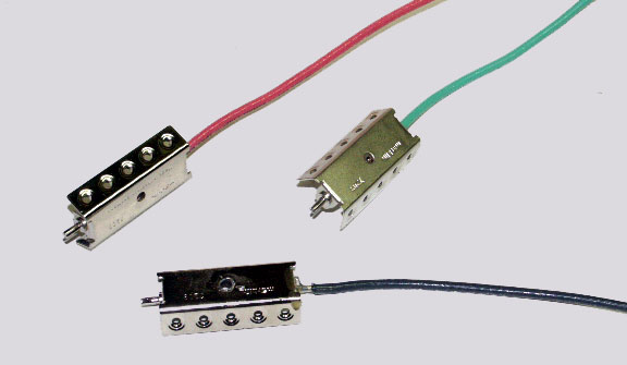
A distribution strip which will be connected to the bare 12 gauge wire using a T tap.
Click on picture to return to description.
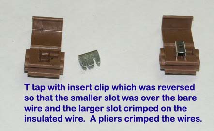
A T tap used to connect a distribution strip to the bare 12 gauge wires.
Click on picture to return to description.
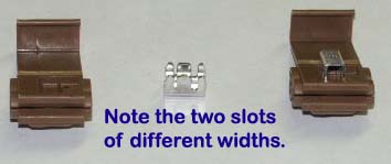
A T tap used to connect a distribution strip to the bare 12 gauge wires.
Click on picture to return to description.
Distribution strips with wires connected for track power and common ground.
Click on picture to return to description.
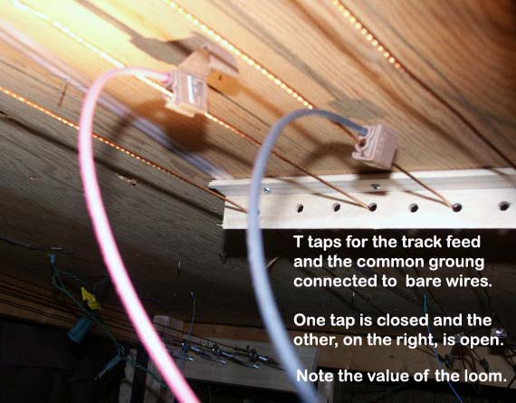
T taps connecting a distribution strip to the bare 12 gauge wires.
Click on picture to return to description.