
S
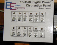
everal pictures of the power suppy that I use for my layout. I have replaced six M rklin transformers and five M rklin boosters with a single unit built by Tim Eckert. The unit delivers 300 watts of power and is has a built-in booster for the entire system. It provides 12 channels (a customized model) for power outputs.The output for each channel is customized to my layout needs. The outputs for the various channels are 50, 65, 84,and 100 watts. Each channel is controlled by a switch and a polyswitch circuit breaker so if one section has a short, unlike the M rklin system, all the other sections or blocks remain powered.
I am only using 6 channels, 4 for power to track sections and 2 for switches and signals. I use the 50 and 65 watt channels for track sections or blocks and for powering switches and signals. My switches and signals have never worked so well because of the dedicated power.
S
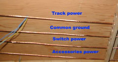
everal pictures of the wiring for my layout. With the a great deal of help from Robert Frownenfeld, Michael Coll-Barth and Bryan Adams, I re-installed all feeders and grounds. I have "before" and "after" pictures my wiring. The underside of my layout is a much, much neater now. I used looms made from corner molding to hold the wires.Each layout section or block is gets power from a separate channel. Each layout section needed four wires, one for a common ground, one for track power, one for switch power and one for accessories power. To wire each section I used bare #12 gauge stranded-wire for each of the three power feeds and for the common ground. The bare copper wires must be kept taunt which made the installation a little more difficult and complex than I had anticipated. Eyelets and turnbuckles were used. The bare wire was first connected to an eyelet and pulled through the looms. The end was then connected to the turnbuckle and the slack was taken up.
I used insulated color coded #12 gauge wire to connect the layout sections to the power panel.
Having bare wires allows you the option of soldering wires from feeder tracks or K83/84's anywhere without long connecting wires. To ensure that I didn't confuse the the bare wires I placed small strips of colored electric tape on the bare wire every 2-3 feet.
For one section, the industrial section, I used insulated #12 gauge wire which I stripped of its insulation every two feet. This process of stripping the insulation in the middle of a wire was a little more difficult than I thought. I used strippers to make two cuts and then a sharp knife to make a longitudinal cut in the insulation. The first layer came off and then I made a similar second cut to remove the second layer of insulation. See the pictures of the finished procuct. After installing these wires in the looms, I soldered a wire from the bare spot to wires connected to a track section or to K 83/84. The wires are color coded - red for power, black for ground, green for switch power.
I used T taps to connect the ditribution strips to the bare and to the insulated wires for common ground, track power and switches. I soldered Marklin wires to the bare wires or to the stripped portion of wires and ran them to tracks and switches or I connected wires for track power, common ground and switches to distribution strips.