DIAGRAMS OF MY OLD LAYOUT
Click on the back arrow to return to the Main Menu.
First let me state that I loved my OLD layout with its size and complexity. I could operate at least six trains on six distinct routes with no chance of a wreck occuring. Space constraints in my new home limited the routes i could run is the layout were only on one level. I solved that problem to some extent by adding two levels, one above and on below. Be sure to visit pictures of my new layout and its construction.
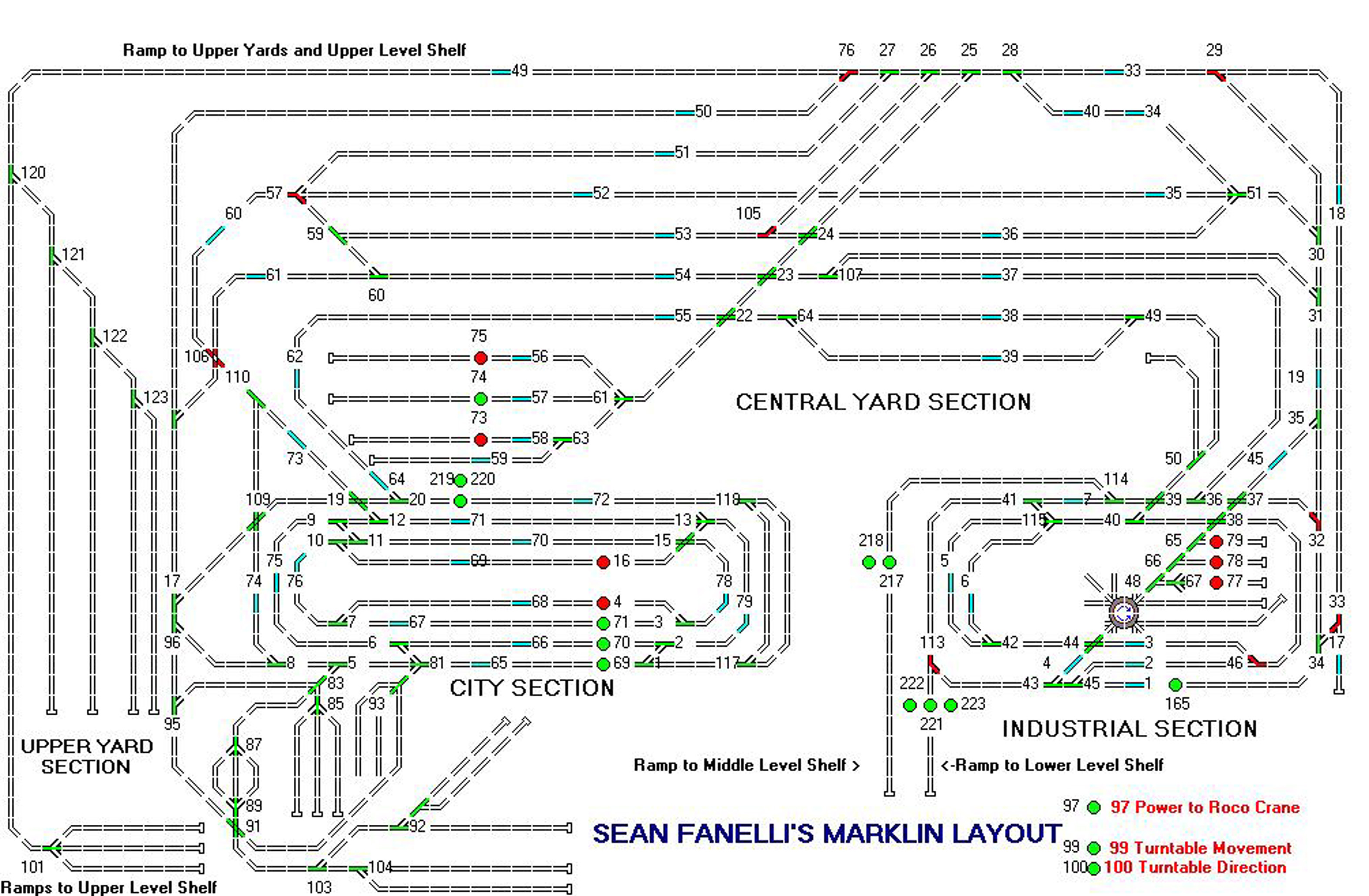
This diagram shows the complete OLD layout. The switches were numbered for a specific digital decoder. The signals were shown as red or green circles with the decoder number next to them. The numbers near the light blue track represented track detectors that sent a signal to the computer when a train passed over it. When this happened, the next series of commands in a route were executed, i.e., a switch was thrown, this train or another train started, or stopped, or a new speed was set, a signal was set to red or green.
This was an updated diagram that reflected the construction of several ramps to my storage unit and the restructuring of the ramp to the Upper Level Yard.
The diagrams below are all drawn using the Layout Design function in TPL. When running in the graphics mode a switch or signal on the layout could be set by placing the mouse cursor on the switch or signal and clicking. The switch or signal will change color from green to red or red to green, as appropriate.
With TPL, the computer control program I once used, you could set switches as you watched a consist visually or on the computer screen by watching the lok passing over contact tracks. Using TPL, you could also run a route or routes in the Graphics mode. As the route called for a switch to be set, the color of the switch changed accordingly. When a train passes over a detector track it changed from light blue to dark blue on the diagram.
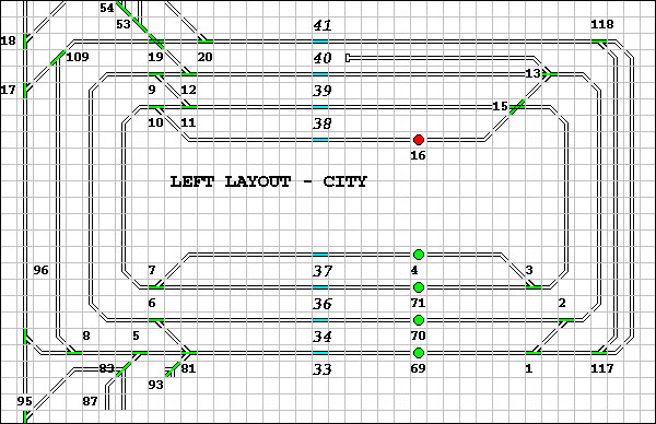
Diagram of the City Section of the Layout.
T
his diagram shows the City Section of the layout. The switches at the top left lead to the Center Section of the layout. The switches at the bottom left lead to a staging yard and to a village. Trains enter from the top left or from the bottom left. Trains on this line will stop at the Calw Station which is at the center bottom of the diagram.
This section has buildings in the middle of this section of the layout with several trains on sidings around the perimeter of the buildings. Several HAG commuter trains run around the inner two tracks of this section. The Lady Wurtemberg runs on the inner track as well. The outer section is a main line that allows traffic to move from section to section.

Diagram of the Center Section of the Layout.
T
his diagram shows the Center Section of the layout. The switches at the bottom left lead to the City Section of the layout. At the top left there is a spur that leads to an upper level staging yard. The top right and the bottom right switches lead to the Industrial Section of the layout.
This section serves as both a staging yard with seven different sidings and as a mainline connection between the city and the industrial sections, and as a connection to the upper level staging yard and the staging yard and village to the left of this section.
This section has several mainline tracks and several passing sidings.
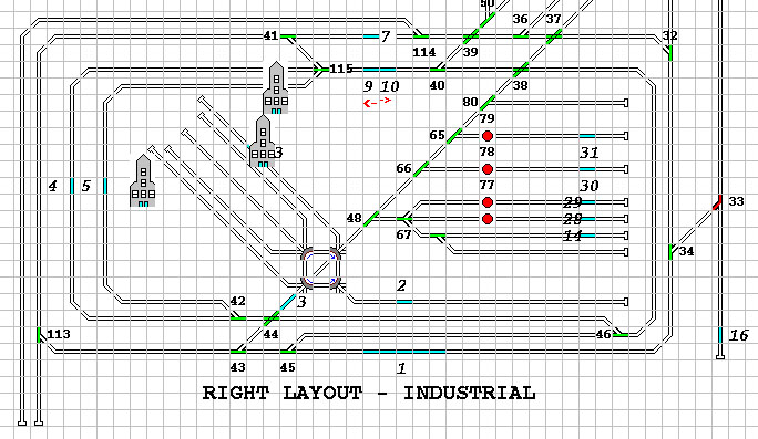
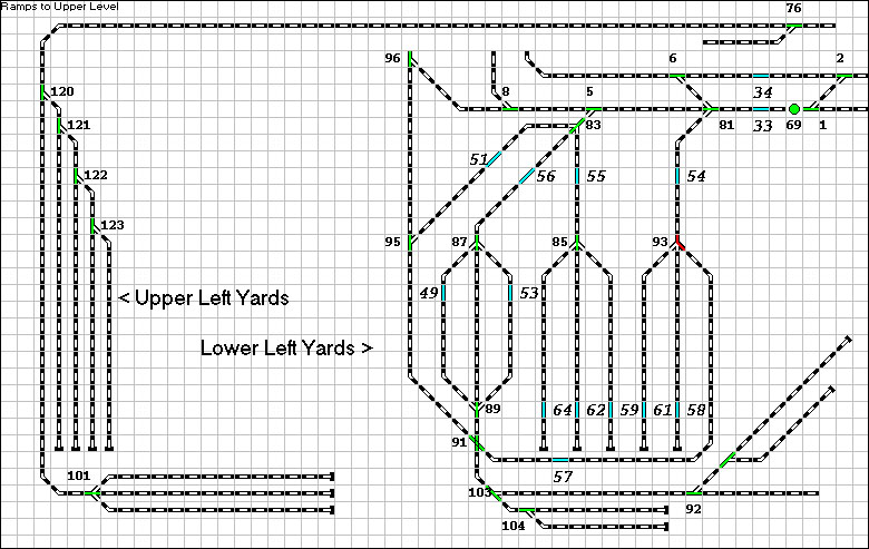
Diagram of the Industrial Section of the Layout.
T
his diagram shows the Industrial Section of the layout. The tracks at the upper left come from the Center Section and lead to the Industrial Section of the layout. Trains could also enter the Industrial Section from the Center Section at a second point at the top middle of this section. This allows control of the trains direction in this section of the layout.On the upper center of the diagram you can see the start of the ramp to the upper-level shelf on the storage unit.
In the lower left you will see the ramp to the lower level shelf on the storage unit.Since the tracks on these ramps are C track the bumpers at the end of the ramp can be easily disconnected and with two straight C tracks I can connect to the upper or lower level of the storage unit.
This section serves as both a staging yard with seven different sidings and as a mainline through the Industrial Section. There was a digitally operated turntable with a three stall roundhouse.
In this staging area is the TEE Express, the Roco crane car, the M rklin Goliath crane, and a number of freight consists. There was a brewery, a Shell Oil petroleum refinery, a large factory, a cement plant and several warehouses.
Diagrams of the Upper Yard Section and the Lower Yard Section of the Layout.
T
hese diagrams show the Upper Yard Section of the layout. The tracks at the upper left come from the ramp on the Center Section. Engines and consist are staged in the Upper Yard. With the use of C track on the ramp and a perfect 4% grade (using Scenic Woodlands foam ramp system.The lower yard has a number of consists. It runs directly into the City Section of the layout.